Our Speeds and Feeds Log is done in Sheets and embedded below. You can edit the table here: Manufacturing Log
The purpose of recording data in this table is to see trends in what makes good feeds and speeds. This information is intended to assist future users of the Shapeoko and to give reccomendations for future cuts. Log any new attempts in here, no matter the change, and don’t be afraid to bash yourself a little bit! Its all a learning experience.
Milling Speed and Feed Calculator
We can change 2 main things while the machine is running:
These effect one big factor: Chip Load
Chip Load: = Feed Rate /(RPM x number of flutes). Chip load is the size of the pieces getting cleared by the machine, or the chips.(IPR, or Inches per Rotation) or Cutting Feed. IPT is Inches Per tooth, and is often reccomended in the tool specifications.
Tool reccomendations are specified for each tool and should be researched (by manufacturer, ect)
SFM, or Surface Feet Per Minute, is also specified in tool parameters, but should be less important on the shapeoko as it tends to reccomend RPMS we can’t achieve (too low) because the shapeoko is so unstable.
Summaries:
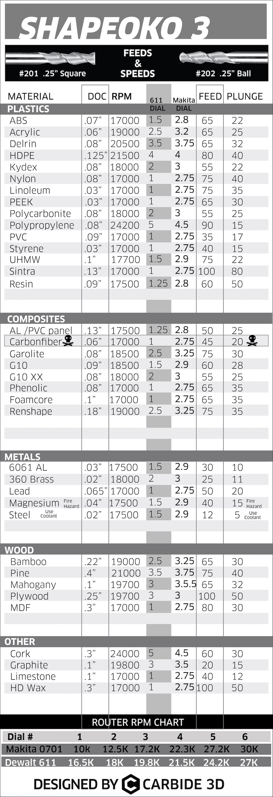
Shapeoko Reccomendations for 3F 1/4” endmill
Material Based IPR Reccomendations
I forgot how important it is to pass this down!
The method: 1) apply blue painters tape to underside of part stock surface. Ensure surface is clean, and that there is a lot of surface area for the glue. 2) Ensure good contact is made, tape is flat, and there are no ridges between the seams. 3) Apply blue painters tape to the wasteboard or cutting surface. 4) apply a //////// pattern of superglue lines, (less than you think). Not much superglue is needed. Maybe space them 0.5” ~ 1” apart. It may be less or more depending on the size of your part. The product of too much glue is a slipping and sliding mess, too little and you your part will move on you. 5) Align the part as best you can to the machine axis. You can try fun things like running the side of a smooth shaft in the cnc and squaring things up that way. You could mark the outline of the part in pencil. You shouldn’t ever count on this alignment being perfect coming off the CNC. It is good practice to machine all the critical faces that matter to you. But how you get things mostly correct is your call.
You can actually do many operations using this method. It works better than you think. Watch the video to see some examples, Titans of CNC has som crazy ones too really push this style of workholding, but I would reccomend an aluminum baseplate if you are doing any serious operations.
It is common in CNC machining to leave an “Onion skin” layer at the bottom of your part. Tabs would be another method to easily hold a part in material. This can be quite a clean method, but requires a good deal of precision to get right. The thick onion skin method has the positive of being much more reliable and precise, but at the cost of material thickeness.
When making 2.5D parts, one can easily use thicker material stock than needed and machine the object with respect to the top surface. Then, in a second operation, the part can be flipped and the bottom surface can now be faced down to the correct height. You can get creative wwith the kind of “reverse” tabs you’ll have to create.
It should go wihtout saying, but you always need to be thinking 10 steps ahead when doing CAM. It is very complicated, especially when you are learning. You will make mistakes, but you will also learn from them when you WRITE THEM DOWN. This isn’t to shame you or embarass you, it is for us to be better machinists in the future.
It is a good idea to create stock that is larger than your real stock. This will help ensure adpatives clear all material something is slightly misaligned, will help facing operations not overcut, and help all mating faces be machined accurately. Our reccomendation is to use the following setup:
It is common for us to use the design tab in fusion to create a custom 2d sketch to highly a specific cut area for facing, or a tab using the Thick Onion method.
Information on wood cutting (particularly MDF) can be found in the wasteboard project section.
Used fusion 360 for CAM and tried to get adaptive clearing set up for the wasteboar but ran into issues. Eventually landed on peck drilling with a chamfer tool to eventuall hand drill all the mounting holes for the wasteboard.
Jack worked on creating a tool library for our current endmills.
Jared made some temporary hold plates and cut the mdf for the machine.
Wasteboard was cut out of 3/4” mdf that can be resurfaced every month or so depending on how marked up it gets. Ideally, there would be scraps placed under cut parts to keep it fresh. The goal of the wasteboard is to provide a machine level surface to mount parts and finish tramming the machine. This is incredibly important when cutting metal, but not so much for wood. The end goal is increasing the accuracy as much as we can of the shapeoko, hence why it has taken so long to get to this point. You have to be diligent about every step along the way because of how many variables there are. Don’t half-ass any of this work, the investment you put in now will save an uncountable number of future issues down the line.
This project deserves much more documentation but today will be a start. Look for future logs
Our main goal was to manufacture the mdf wasteboard that sits on top of the shapeoko. This board will provide mounting locations with these 1/4-20 T nuts. Next time I would go with the screw in type of insert because these need to be countersunk. This requires us to do 2 operstions because the bolts that mount the wasteboard to the Shapeoko will also need to be countersunk. We are not sure how to accomplish this yet, but we have thought of some ideas to get the positions right on the machine. It is likely going to be a manual drill with a centerpunch, but it would be so nice to perfectly align the bolt holes to the X and Y of the machine. We have to figure out how to get it perfect.
We ran into a few issues with the tram plate to the spindle not being tightened, this resulted in imperfect bore holes for the T nuts. After fixing that issue, the left side Y belt was incredibly loose, leading to even worse counterbores. We ended up needing to re-face the wasteboard… but that is what it is for! It is quite a tough thing trying to set up a full machine shop at home. There are so many odds and ends that end up being really important to get everything done right. You may have a CNC, but we need a way to mount stuff to it!
See cut log from today for fun notes about our new heat generator.
We cut way too slow today in aluminum. Our RPMs were very high at 18k to be “safe” but that ended up hurting us. it would be a good idea for us to buy clamps, take lighter DOC, and increase our feed rate. This machine can handle quite a bit thrown at it. It’s ok not to baby it, but it’s hard to build that confidence when we really are just learning what it can do. On the bright side, the surface finish of the torn up part ain’t too (on 1 side).
Notice in this linked video how it did at the beginning, but it quickly got too hot to do anything. It throw chips at the very beginning, that is what we are looking for to get that heat away from the part.
PHOTO OF SHINY ALUMINUM FROM TODAY